|
|
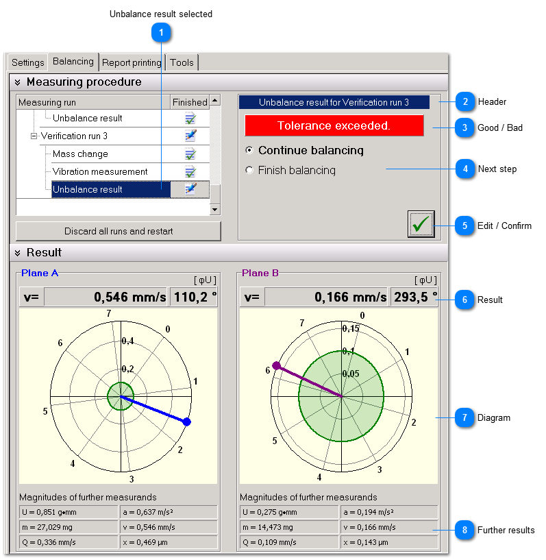
After finishing the test runs you will get the first unbalance result. Further unbalance results are shown after the verification runs.
 Unbalance result selected
| |
 Header
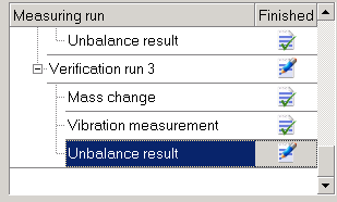
Measuring run, for example
-
Unbalance result for Test run Plane A (in case of Single-Plane-Balancing)
-
Unbalance result for Test run Plane B (in case of Two-Plane-Balancing)
-
Unbalance result for Verification run 1
-
| |
 Good / Bad
| |
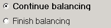
 Next step
You may decide what to do next. If the tolerance limit was exceeded VM-BAL will suggest to continue balancing. However, you can always finish the procedure. | |
 Edit / Confirm
|
|
Click this button to confirm your entries and proceed to the next run.
|
|
|
The confirm button turns into an edit button. You can return to the mass edit menu as long as the next mass change has not been finished yet.
| | |
 Result
The result is shown as magnitude and angle according to the balancing aim. The angle corresponds to the measured unbalance. If the balancing aim was a reduction of vibrations the angle may differ from the angle measured vibration display because of dynamic rotor properties. To maintain concurrence with the angles used during unbalance correction the unbalance angle is here also used for vibration indication. | |
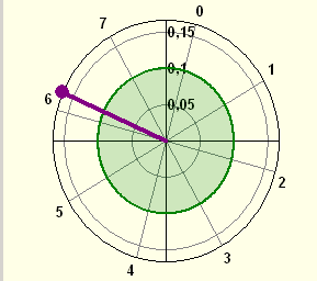
 Diagram
|
|
The diagram shows magnitude and position of the unbalance with regard to the tolerance limit indicated as a green circle.
| | |
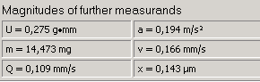
 Further results
|
|
In addition the results according to the balancing aim VM-BAL shows other measurands providing information about the balancing condition of the rotor. | | |
|
|