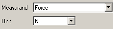
Frequency response function
To determine the frequency response function (FRF) an input and an output signal is needed.
 Channel display
|
|
At least two channels are needed to determine the frequency response function. According to the selected FRF mode the signal inputs have to be assigned to channel IN and channel 1.
| |
|
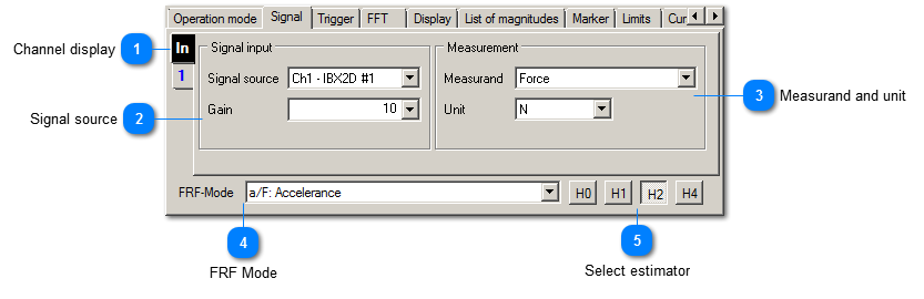
 Signal source
|
|
Signal source selects the physical input for the vibration signal. Gain is used for the manual range selection. If a selected value does not fit the current FRF mode it is highlighted in yellow.
| |
|
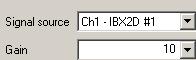
 Measurand and unit
The connected sensor determines the measurand. Additionally, VM-FFT+ can handle the integrated measurands. Therefore, vibration velocity and displacement are also offered as measurands when an accelerometer is connected.
The units are listed matching the measurands. The characteristic value should neither rise above 10 000 nor fall below 0.001 permanently. This should be noted while selecting a unit.
If the measurand is highlighted yellow, the selected signal input or the measurand does not fit the selected FRF mode.
|
|
 FRF Mode
Different FRF modes are available:
-
-
-
-
-
F/v: Mechanical Impedance
-
-
-
~: Proportional Quantities
-
|
|
 Select estimator
Estimators are used in order to improve the determination of the frequency response function. These are used to distinguish the signal from noise at low input or output levels. The estimator can also be selected after the measurement. The results of all estimators are formed after an impulse.
|
|