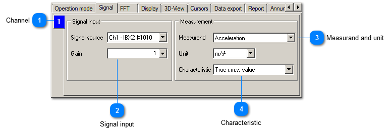
This control tab offers settings for the signal to be measured.
 Channel
|
|
VM-FFT 3D is a one-channel analysis tool. If more channels shall be viewed simultaneously, the instrument can to be cloned.
|
|
|
By right-clicking on the channel, its color in the diagram can be adjusted (Change color).
| |
|
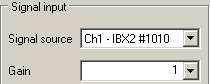
 Signal input
|
|
Signal source selects the physical input for the vibration signal. Gain is used for the manual range selection.
| |
|
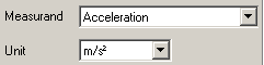
 Measurand and unit
The connected sensor determines the available options. Velocity and displacement are calculated from acceleration by integration (VM-FFT 3D+ only). The unit should be selected in a way that the measuring value does not drop below 0.001 permanently.
|
|
 Characteristic
The following characteristics are available:
|
Peak value:
|
The height of the FFT line represents the amplitude of the corresponding sinusoidal signal.
|
|
Peak-to-peak value:
|
The height of the FFT line represents the peak-to-peak amplitude of the corresponding sinusoidal signal.
|
|
True RMS value:
|
The ehight of the FFT line represents the true RMS value of the corresponding sinusoidal signal.
| |
|