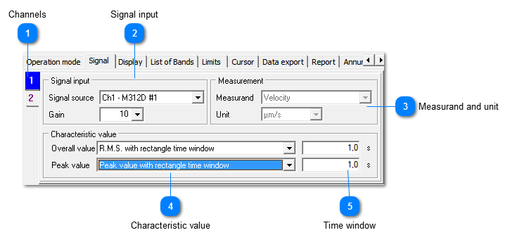
Signal settings for VC and Nano lines
This panel shows the relevant settings for the measuring channel. They are identical for VC and Nano lines.
 Channels
|
|
Signal conditioning can be set for each channel individually. VM-OCT can display different characteristics for one sensor.
The number of tabs depends on the entered channel number. The channel color can be changed by right mouse click.
|
|
|
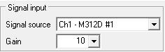
 Signal input
|
|
Selects the used M302/M312 device and the inputs with connected accelerometers.
The gain setting determines the measuring range.
|
|
|
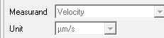
 Measurand and unit
|
|
For the measurement of VC and Nano lines vibration velocity in µm/s is the relevant measurand.
It is preset and cannot be changed.
|
|
|
 Characteristic value
The diagram can display RMS and peak values simultaneously. Peak values are indicated in brighter color on top of the RMS bars. The following calculation modes are available:
RMS (calculated for the entered time window), relevant for measurements according to VDI 2038-2.
|
|
... with rectangular time window
|
Displays the mean value during the past sliding time window
|
|
... with exponential time window
|
Higher mean values are indicated immediately and decay with the entered time
|
|
|
|
off
|
No peak display
|
|
... with rectangular time window
|
Displays the peak value during the past sliding time window
|
|
... with exponential time window
|
Higher peak values are indicated immediately and decay with the entered time
|
|
Peak hold
|
Maximum peak value since start of VM-OCT
|
|
|
 Time window
|
|
Time window for RMS and peak calculation, 0.1 to 100 s
| |
|