|
|
The signal processing settings are only visible after you activated them in the displaying settings.
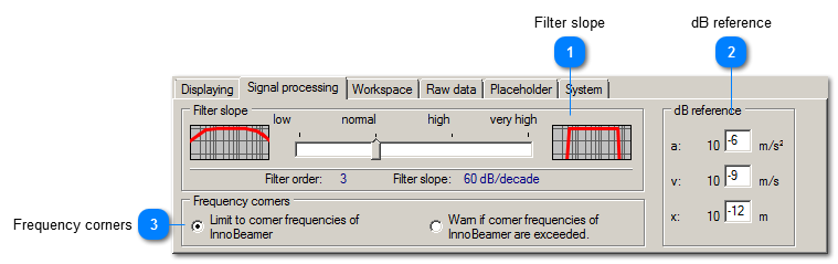
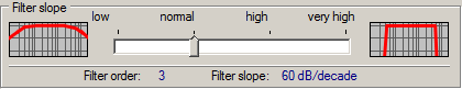
 Filter slope
The filter slope determines how much VibroMetra attenuates the magnitudes of instruments with freely adjustable filters out of the passband. The passband is limited by means of the fmin and fmax settings in the instruments ( example). The higher the filter slope, the stronger the separation between passband and cutoff region.
The filter slope is set to 60 dB/decade by default. It means that vibrations at a frequency 10x higher than fmax or 1/10 of fmin are reduced to one thousandth of their original magnitude. A filter slope of 60 dB/decade corresponds to specifications in standards, e.g. DIN ISO 2954 which standardizes measurement equipment for vibration measurement on rotating machinery acc. to ISO 10816.
The filter slope can be set up to 1280 dB/decade. The necessary filter order 64 could not be reached with conventional electronic components. However, by implementing the filter by means of digital signal processing and thanks to the high internal precision, VibroMetra allows such slopes. A high filter slope can be useful when extracting single frequencies from a mix of periodical signals. In contrast, a high filter slope can be disadvantageous with transient signals, e.g. shocks, because the filter reacts with longer duration transients depending on the selected lower limit frequency fmin..
The type of bandpass filter used in VibroMetra is Butterworth. This type of filter does show no ripples in the passband of the amplitude frequency response. It is also stipulated in standards for vibration measurement equipment (DIN 45662, DIN ISO 2954).
The filter slope does not influence instruments which are directly measuring acc. to a certain standard. For instance, the filter slope of measuring equipment for building vibration is set to 40 dB/decade according to DIN 4150-3. So this slope is integrated in the instrument VM-STRUC and it is not influenced by the global filter slope setting. | |
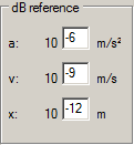
 dB reference
The measurands vibration acceleration, velocity or displacement can be displayed in absolute units, but also as reference measurand. In case of displaying as reference measurand, the measured value is displayed as percentage of a fixed reference value. These reference values can be entered for:
-
a: vibration acceleration
-
-
x. vibration displacement
The default values are based on standard specifications. But they can be adjusted.
VibroMetra uses the logarithmic dB as unit for the reference measurand.
| |
 Frequency corners
Limit to corner frequencies of USB device
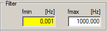
The limit frequencies for bandpass filter can be adjusted freely in the VibroMetra instruments. However, this freedom is limited by the limit frequencies of the measurement hardware (M302 / M312). In case of using an M312, these limits are 0.1 ... 40 000 Hz. The restriction to the corner frequencies (resp. cutoff frequencies*) is the default setting.
Warn if corner frequencies of USB device are exceeded
For special analysis, it can be useful to set the the limit frequencies in the bandpass filter beyond the corner frequencies of the measurement hardware. In this case, VibroMetra will allow the bandpass filters for fmin to be below the lower limit frequency of the measurement hardware. In this case, the input field will be colored yellow as a warning.
* Cutoff frequency = special limit frequency with an amplitude attenuation of -3 dB.
| |
|
|