|
|
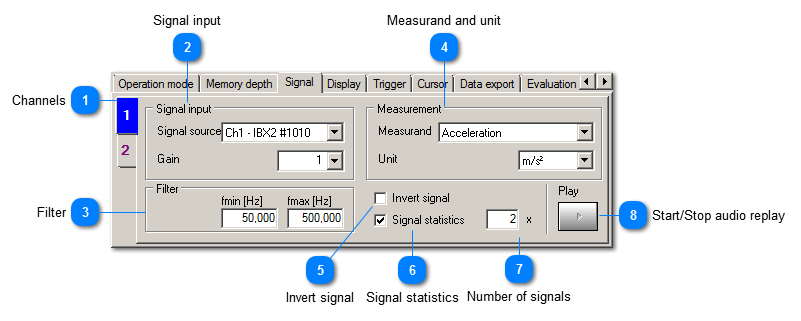
 Channels
|
|
All settings can be entered independently for each channel. For example, you may use different filters. The number of tabs depends on the number of active channels.
|
|
|
More settings are available when right-clicking on the channel. Thereby its color in the diagram can be adjusted (Change color) or its settings can be transferred to other channels (Copy settings to other channels).
| | |
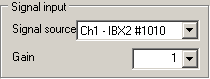
 Signal input
|
|
Selects the physical input and the gain of the USB device.
| | |
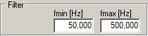
 Filter
|
|
Here you adjust the frequency range of the displayed value fmin to fmax.
| | |
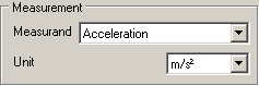
 Measurand and unit
The connected sensor determines the available options. Velocity and displacement are calculated from acceleration by integration (VM-SCOPE+ only).
The unit should be selected in a way that the measuring value does not drop below 0.001 permanently.
| |
 Invert signal
Inverts the sign of the measured signal. This can be useful, for example, to compensate the mounting direction of an accelerometer.
| |
 Signal statistics
| |
 Number of signals
| |
 Start/Stop audio replay
The vibrations of the displayed time range (Pre-/Posttrigger) can be replayed acoustically. To this end, data of the whole trigger period have to be available. The replay can be interruppted by the Stop button. The vibration signals can be exported as wave file (.wav). | |
|
|