|
|
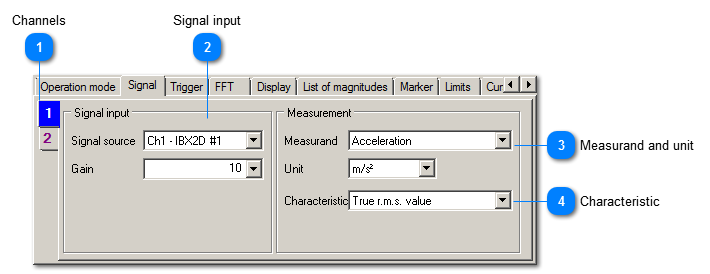
 Channels
|
|
All settings can be entered independently for each channel. For example, you may use different filters. The number of tabs depends on the number of active channels.
|
|
|
More settings are available when right-clicking on the channel. Thereby its color in the diagram can be adjusted (Change color) or its settings can be transferred to other channels (Copy settings to other channels).
| | |
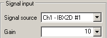
 Signal input
|
|
Selects the physical input and the gain of the USB device.
| | |
 Measurand and unit
The connected sensor determines the available options. Velocity and displacement are calculated from acceleration by integration (VM-FFT+ only).
The unit should be selected in a way that the measuring value does not drop below 0.001 permanently.
| |
 Characteristic
The following characteristics are available:
|
Peak value
|
The height of the FFT line represents the amplitude of the corresponding sinusoidal signal.
|
|
True RMS value
|
The height of the FFT line represents the true RMS value of the corresponding sinusoidal signal.
|
|
Peak-to-peak value
|
The height of the FFT line represents the peak-to-peak amplitude of the corresponding sinusoidal signal.
| | |
|
|