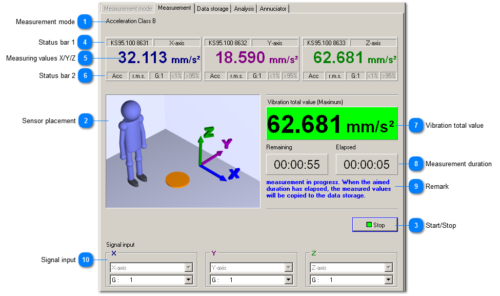
While measuring, VM-SHIP displays the vibration total value and a colored assessment.
 Measurement mode The selected measurement mode is shown once again. |
|
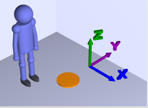
 Sensor placement
|
|
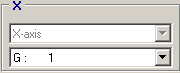
The image shows the body's coordinate system. The sensor has to be mounted in a way that its axes are aligned accordingly resp. you have to select the axis accordingly in the sensor automatic. | |
|
 Start/Stop This button starts resp. stops the measurement. |
|
 Status bar 1 |
|
 Measuring values X/Y/ZThe vibration value (weighted interval RMS value) for the axis is displayed here.
|
|
 Status bar 2The second status bar shows:
|
|
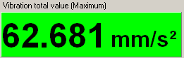
 Vibration total valueThe maximum of the values from the single axes is displayed as vibration total value.
|
|
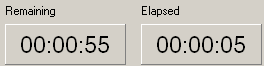
 Measurement durationVM-SHIP displays elapsed and remaining measurement duration. The elapsed measurement duration counts with minus sign from start delay to 00:00:00. Afterwards, the elapsed measurement duration counts up to the aimed measuring time. The measurement is stopped when it reaches the aimed measuring time. |
|
 RemarkThis remark informs about the current state.
|
|
 Signal inputAt the signal input, you select the measuring channel and configure the measuring range. If you activated the sensor automatic VM-SHIP selects the measuring channel automatically. |
|