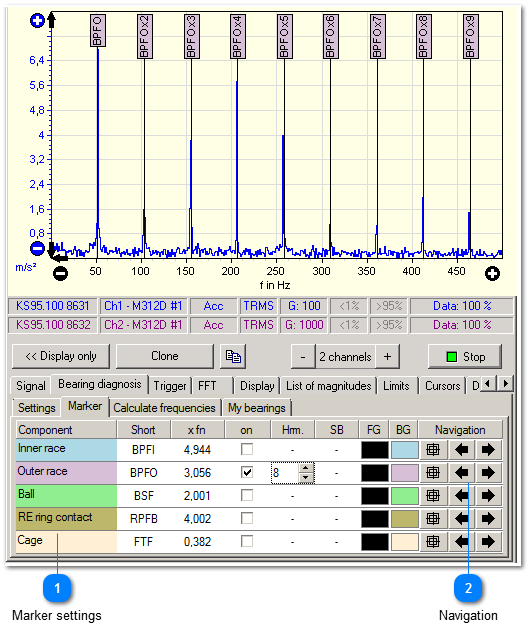
Markers help to detect particular bearing faults from the spectral diagram.
 Marker settings
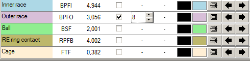
The marker settings can be adjusted separately for each component of the bearing. The columns feature the following settings:
|
Component
|
This column lists up the bearing components. It cannot be changed.
|
|
Short
|
An abbreviation for the bearing component.
|
|
x fn
|
Rotational frequency factor. The damage frequency is specified as a factor to the rotation speed. This way, the damage frequency is characterized correctly for each rotation speed.
|
|
on
|
Activates (resp. deactivates) the marker in the measurement chart.
|
|
Hrm.
|
Number of harmonics to be indicated as a marker in the measurement chart.
|
|
SB
|
Number of side bands to be indicated in the measurement chart. Side bands can only be activated for components which technically can possess side bands.
|
|
FG
|
Foreground color. The text in the markers will be written in this color.
|
|
BG
|
Background color of the markers.
|
|
Navigation
|
|
|
|
The bearing currently used can be applied to the bearing table by selecting Copy to my bearings. This is useful if the damage frequencies have been calculated by VibroMetra by entering the geometric dimensions of the bearing. | |
|
 Navigation
By means of the navigation buttons you can quickly select the magnitudes of the envelope analysis.
|
|
When clicking the cross hairs, VM-FFT directly zooms in on the damage frequency of the respective bearing component.
|
|
|
By means of the arrows, the measurement chart is set to the previous resp. next harmonic.
| |
|