|
|
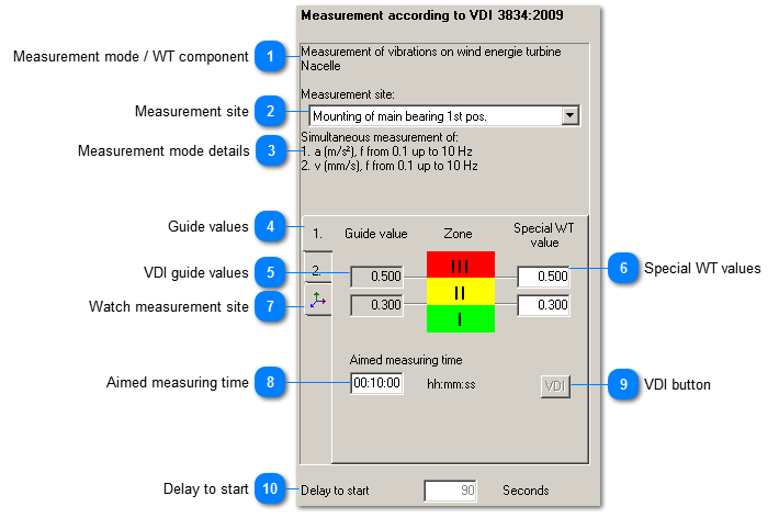
Configuration options for the measurement mode
 Measurement mode / WT component
This field shows the selected measurement mode on the selected WT component. | |
 Measurement site
This drop-down menu lists up all measurement sites for the respective WT component. Some components are measured on several site, e.g. the generator.
| |
 Measurement mode details
|
|
For greater certainty concerning the selected measurement mode, the following details are displayed:
| When selecting combined measurement, several measurement modes which have to carried out on the same measuring point are carried out simultaneously. The measurement modes are numbered consecutively.
| |
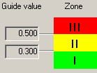
 Guide values
|
|
In case of combined measurements, several measurands are recorded simultaneously. They have different guide values. By means of the tabs you can see the different guide values. The numbers stand for the measurement modes described in the measurement mode details. | | |
 VDI guide values
|
|
Show the VDI 3834 guide values for the limits of the evaluation zones. These zones have the following meaning:
|
III
|
Vibrations within this zone are generally regarded as so dangerous that damage to the WT and its components could occur.
|
|
II
|
The WT and its measured components are not normally regarded as being suitable for running in continuous operation. Investigation is recommended to detect the causes of the vibration excitations and decide whether design and operating conditions of the equipment in question permit continuous operation.
|
|
I
|
The WT and its measured components are regarded as suitable for running in continuous operation with these vibratory stresses.
| | | |
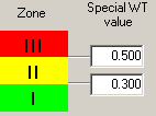
 Special WT values
|
|
The contracting parties can agree to use other (higher or lower) values for the zone limits of certain WTs. It is necessary that the manufacturer gives reasons for this decision and - in case of higher limit values - confirms that the WT or the component can be operated with higher vibration values.
You can enter the changed values for the zone limits in the respective fields. However, the VDI guide values remain visible to make it possible to return to them. | | |
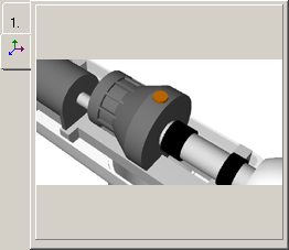
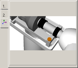
 Watch measurement site
 By clicking on this tab, the measurement site for the selected measurement mode is shown graphically.
Beispiele:
| |
 Aimed measuring time
|
|
To obtain correct result, a certain minimum measurement duration must be adhered. But the measurement duration can also be longer than this minimum duration. If you changed the aimed measuring time, you can enter the minimum measurement duration acc. to guideline by clicking the VDI button. | | |
 VDI button
|
|
By clicking this button, you enter the minimum measurement duration acc. to the guideline in the aimed measuring time. | | |
 Delay to start
Right after having been switched on, vibration measurement equipment usually shows transient effects. During this time, the measurement signal is not yet displayed correctly. The start delay makes it possible to react. The lower the lower limit frequency of the filter, the longer these transient effects will last (90 s for measurements with a lower limit frequency of 0.1 Hz).
| |
|
|