Measuring channel management
VibroMetra can be operated with one single measuring channel, but also with 32 channels. The management of measuring channels provides an overview.
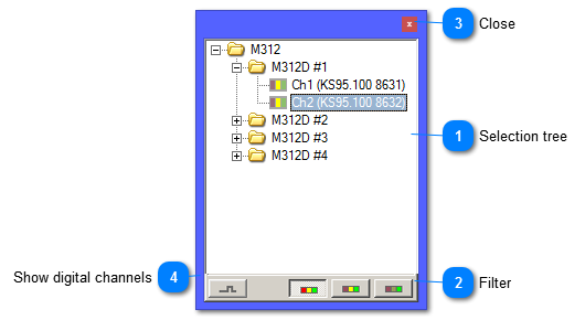
 Selection tree
|
|
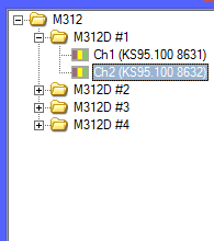
The selection tree shows all devices incl. their measuring channels. The devices are sorted acc. to their type.
The left picture shows the device type M312. There are 2 devices of that type, their serial numbers are 1011 and 1012. Each device provides two measuring channels. Device 1011 displays its channels. These measuring channels have been named individually (X-axis and Y-axis). On the left of the channel name, there is a status indicator in traffic light colors:
|
red:
|
This measuring channel belongs to a device which is not connected at the moment.
|
|
yellow:
|
This measuring channel belongs to a connected device and it is ready for measuring. However, the channel is not measuring yet.
|
|
green:
|
This measuring channel is currently measuring.
| | Mouse operation
-
A double click on a device type opens the properties window of the respective device type. -
-
A double click on a measuring channel opens the properties window of the respective channel. -
A right click on a measuring channel opens its context menu.
|
|
 Filter
|
|
You can restrict the list of measuring channels, e.g. to channels which are currently measuring (green activity indicator).
| |
|
 Close
|
|
This button closes the window.
| |
|
 Show digital channels
|
|
Blends in the digital trigger channels.
| |
|