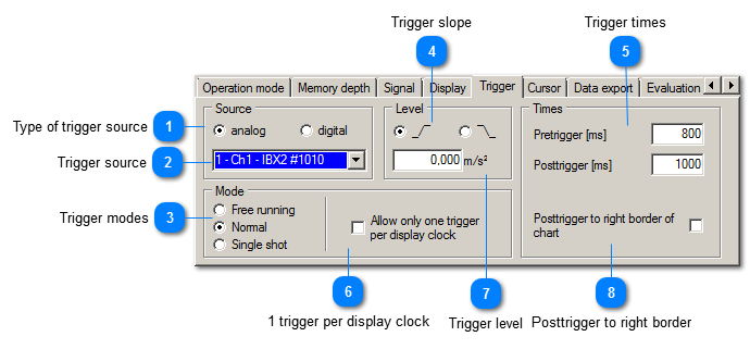
The trigger settings determine the starting conditions for a new measurement.
 Type of trigger source
|
|
Trigger sources can be the analog input signals or the digital inputs of the USB devices.
| |
|
 Trigger source
|
|
This drop-down list shows all trigger sources of the selected type, e.g. all channels of the instrument. | |
|
 Trigger modes
|
|
Behavior after recording:
-
Free running: The trace will continue to run trough the diagram -
Normal: The trace will freeze till the next trigger event -
Single: VM-SCOPE stops, freezes the trace and does not trigger again.
| |
|
 Trigger slope
|
|
Triggering at rising ( _/¯ ) or falling ( ¯\_ ) signal slope
| |
|
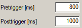
 Trigger times
|
|
Length of recording before and after the trigger event
| |
|
 1 trigger per display clock
|
|
The number of performed triggering can be limited to one trigger per display clock.
| |
|
 Trigger level
|
|
Trigger level for analog sources
| |
|
 Posttrigger to right border
|
|
Activate this checkbox to set the posttrigger time automatically to the right end of the time axis.
| If this feature is not activated recording duration can be manually set by the posttrigger and the signal trace may reach outside the visible diagram range.
|
|