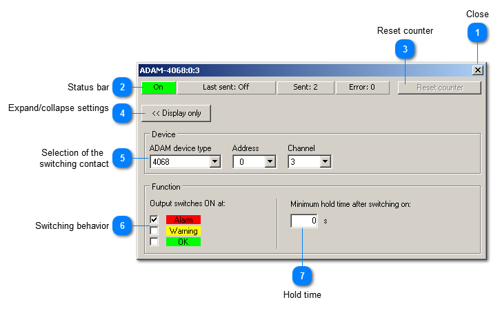
Configuration of a digital output
Each digital output can be configured individually.
 Close
 This button closes the window. But it can be opened again, for instance by a double click in the selection tree. Only deleting the annunciator will erase it permanently. |
|
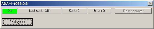
 Status bar
The status bar indicates
-
-
-
-
number of errors occured when sending commands
|
|
 Reset counter
This button zeros the counter for the errors.
|
|
 Expand/collapse settings
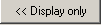 This button expands/collapses the setting area.
The annunciator uses less space on the screen in collapsed state.
|
|
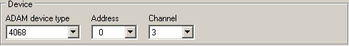
 Selection of the switching contact
In this area, you select the concrete switching contact.
-
All detected device types are listed up. -
All devices of the selected type are listed up. They are represented by their addresses since there might be several devices of the same type. -
Finally you can select the switching channel of the selected device (most devices feature several digital outputs).
|
|
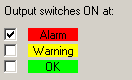
 Switching behavior
In this area, you decide at which state the digital output is to switch on. The output switches off if the connected instrument shows a different state.
|
|
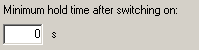
 Hold time
You can enter a minimum hold time after switching on to make sure that slower successive devices are able to recognize the switching state.
|
|