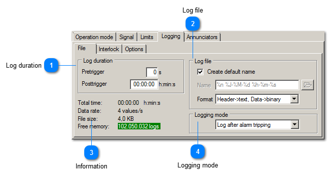
Log file
Here you enter file name, folder and file type.
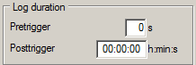
The option Create default name automatically generates a file name as follows:
year-month-day-hour-minute-second VM-REC ID. The default folder is <your VibroMetra folder>\Data\M302/M312 serial number.
Alternatively you can enter your own file name, including variables.
These are the available file formats:
|
Header>text, Data->binary
|
A single file is generated with header data in text format and recording data in binary format.
|
|
Header->text, Data->text
|
Both header and data are saved in text format in a single file.
|
|
1: Header->text, 2: Data->binary
|
Two files are generated, one containing the header data as text, the other containing binary data.
|
Header example:
Version=1.8
VM-REC version number
Pretrigger=5
Pretrigger time in seconds
Posttrigger=30
Posttrigger time in seconds.
SampleRate=10000
SampleRate in samples per second
NumChannels=3
Number of active channels
Channel settings
Settings for channel 1, identified by ending "_1".
InputID_1=K1 - IBL2 #1000
channel number, device type and serial number
InputName_1=Lager 12
Channel name
Sensor_1=KS80 3346
Sensor name
Measurand_1=0
Index of the selected measurand in the menu, starting with 0
MeasurandName_1=acceleration
Measurand as text
Unit_1=1
Index of the selected unit in the menu, starting with 0
UnitName_1=mm/s²
Unit as text
Parameter_1=5
Index of the selected characteristic in the menu, starting with 0
ParameterName_1=True RMS
Characteristic as text
fmin_1=0.3
Lower filter frequency
fmax_1=200
Upper filter frequency
LimitMax_1=75
Upper alarm limit
LimitMin_1=0
Lower alarm limit
UpperAdd_1=10
Upper bar graph extension in percent
LowerAdd_1=0
Lower bar graph extension in percent
After channel 1 follow the settings of the other active channels (NumChannels), marked with "_2" etc.
Measuring data
These fields specify the data format:
DataType=binary
binary or text format
DataStart=1024
Byte position of the first data byte in binary mode, first text line in text mode
DataSize=4
Data type, 4 = 4 byte floating point numbers (float), 8 = 8 byte floating point numbers (double)
There is no DataSize in text format where the values are separated by line separators.
After this the actual data follows in the order of channels (example for 3 channels):
value 1, channel 1; value 1, channel 2; value 1, channel 3;
value 2, channel 1; value 2, channel 2; value 2, channel 3;
value 3, channel 1; value 3, channel 2; value 3, channel 3;
value 4, channel 1; value 4, channel 2; value 4, channel 3;
...
To program external software for the reading of data you need to check DataType to identify the type of data (binary / text). DataStart is used to set the pointer to the start position. DataSize determines the size (float/double). With this information reading can be performed. Header data, like MeasurandName and UnitName, can be used for diagram text etc. Time axis information is derived from SampleRate.
To calculate the amount of data, add Pretrigger and Posttrigger from the header and multiply by SampleRate and NumChannels.
|