|
|
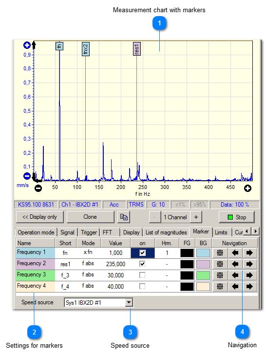
By the use of markers fixed frequencies and the current speed can be highlighted in the spectrum.
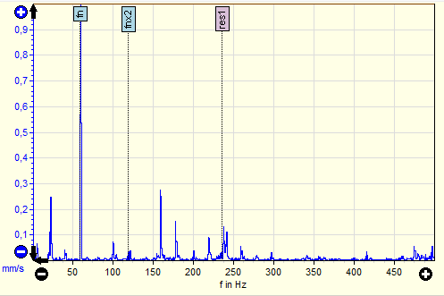
 Measurement chart with markers
The selected markers appear in the measurement chart.
| |
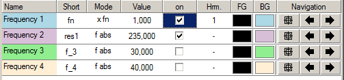
 Settings for markers
The settings can be made for each marker separately. The columns offer the following settings:
|
Name
|
Name of marker, freely selectable.
|
|
Short
|
An abbreviation for the marker that is displayed in the diagram, freely selectable.
|
|
Mode
|
Speed factor x fn. The marker is specified as factor to speed. Fixed frequency f abs. A marker is set at a fixed frequency.
|
|
Value
|
Disclosure of the multiple of the speed frequency (x fn) or entering any frequency (f abs).
|
|
on
|
Activates (resp. deactivates) the marker in the measurement chart.
|
|
Hrm.
|
Number of harmonics to be indicated as a marker in the measurement chart.
|
|
FG
|
Foreground color. The text in the markers will be written in this color.
|
|
BG
|
Background color of the markers.
|
|
Navigation
|
3 navigation buttons..
| | |
 Speed source
Selecting the speed source to display speed markers (and multiple).
| |
 Navigation
By means of the navigation buttons you can quickly select the magnitudes of the envelope analysis.
|
|
When clicking the cross hairs, VM-FFT directly zooms in on the damage frequency of the respective bearing component.
|
|
|
By means of the arrows, the measurement chart is set to the previous resp. next harmonic.
| | |
|
|