
 Signal Conditioners
 Vibration Meters
 Vibration Calibrators
 Human Vibration
 Building Vibration
 PC Data Acquisition
 Cables and accessories
4. IEPE Standard
Metra manufactures many accelerometers featuring a built-in preamplifier. It transforms the high impedance charge output of the piezo-ceramics into a low impedance voltage signal which can be transmitted over longer distances. Metra uses the well-established IEPE standard for electronic accelerometers ensuring compatibility with equipment of other manufacturers. IEPE stands for “Integrated Electronics Piezo Electric”. Other proprietary names for the same principle are ICP®, CCLD, Isotron®, Deltatron®, Piezotron® etc.
Theory of Operation
The built-in circuit is powered by a constant current source (see figure). This constant current source may be part of the instrument or a separate unit. Both supply current and voltage output are transmitted via the same coaxial cable. A positive bias voltage arises at the sensor output. The vibration signal is transmitted back to the supply as a modulated bias voltage. The capacitor Cc removes the sensor bias voltage from the instrument input providing a zero-based AC signal. Since the output impedance of common IEPE-compatible transducers is less than 100 ohms, the cable may be up to several hundred meters long without compromising signal quality. Inexpensive standard coaxial cables can be used instead of expensive low-noise cables.
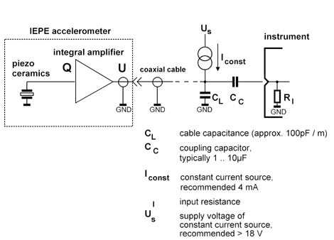
The constant current may vary between 2 and 20 mA (not to be confused with 4 to 20 mA standard). The lower the constant current the higher the output impedance and, therefore, the susceptibility to EMI. A constant current value of 4 mA is a good compromise in most cases.
The bias voltage, i.e. the DC output voltage of the sensor without excitation, is typically between 12 and 14 V. It varies with supply current and temperature. The output signal of the sensor oscillates around this bias voltage. It can never become negative. The upper limit is set by the supply voltage of the constant current source. This supply or compliance voltage should be between 24 and 30 V. The lower limit is determined by the built-in amplifier. Metra guarantees an output span of > ± 5 V.

Low Power IEPE
Particularly for battery-operated equipment it may be unfavorable to provide a sensor supply with 4 mA constant current from a 24 V compliance voltage, requiring a power of 100 mW. For this reason Metra has introduced a low-power version of the IEPE standard, which is applied in several accelerometers and instruments. Low Power IEPE accelerometers usually have a bias voltage of 4 to 8 V. So a compliance voltage of 10 to 12 V is sufficient. The constant current supply may be as low as 0.1 mA, depending on the transducer model. This can reduce the power consumption of the transducer by up to 99 %.
Frequency Performance
The lower frequency limit of Metra´s transducers with integrated electronics is 0.3 Hz for most shear and bender accelerometers and 3 Hz for compression sensors. The upper frequency limit mainly depends on the mechanical properties of the sensor.
In the case of longer cables, their capacitance should be considered. Typical coaxial cables supplied by Metra have a capacitance of approximately 100 pF/m.
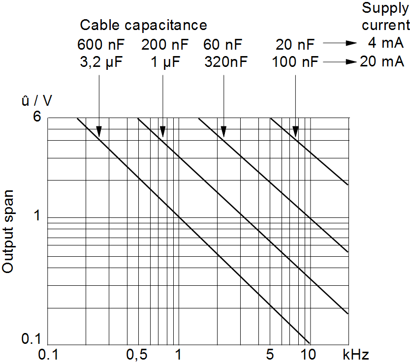
The diagram below shows the maximum output span of an IEPE transducer over the frequency range for different cable capacitances and supply currents. With increasing cable capacitance the output span becomes lower. The reason for this influence is the reduced slew rate of the built-in amplifier at higher load capacitances. With very long cables the full output span of ± 6 V can only be reached at frequencies up to a few hundred Hertz. This effect can be compensated within certain limits by increasing the IEPE supply current. For a cable capacitance up to 10 nF (100 m standard coaxial cable) and 4 mA supply current the reduction of the output span can be neglected.
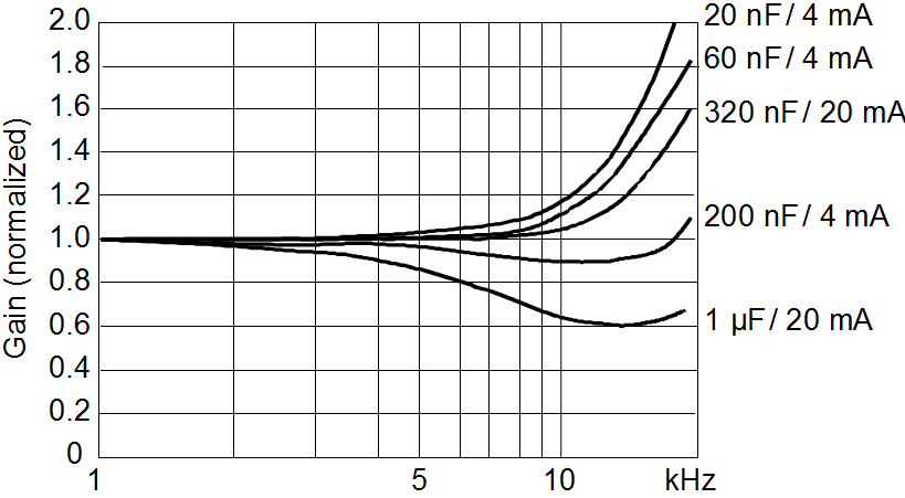
The following diagram shows the typical frequency response of the sensor electronics under the influence of different cable capacitances and supply currents. At higher capacitances the upper frequency limit drops. The reason is the low pass filter formed by the output resistance and the cable capacitance At 4 mA the cable capacitance can be up to 50 nF (500 m standard coaxial cable) without reduction of the upper frequency limit.
Today in most applications IEPE accelerometers are preferred. However, charge mode accelerometers can be superior in some cases. The following table shows advantages and drawbacks of both sensor types.
| IEPE output | Charge output | |
Advantage | Constant sensitivity regardless of cable length and cable quality Low-impedance output can be transmitted over long cables in harsh environments No special cables needed Intrinsic self-test function Withstands better harsh conditions like dirt and humidity | No power supply required – ideal for battery powered equipment No noise, highest resolution Wide dynamic range Higher operating temperatures Smaller sensors possible |
Disadvantage | Constant current excitation required (reduces battery operating time) Inherent noise source Upper operating temperature limited to <120°C | Limited cable length (< 10 m) Special low noise cable required Charge amplifier required |