Theory and Standards
Would you like to familiarize yourself with the basic concepts of piezoelectric vibration measurement technology? By means of the provided information you will be able to select, mount and connect a vibration transducer. If you do not yet have any experience with piezoelectric vibration transducers, we recommend reading these pages in sequence as a learning course.
5. Accelerometer Characteristics
Metra utilizes for factory calibration a modern PC based calibration system. The calibration procedure is based on a transfer standard which is regularly sent to Physikalisch-Technische Bundesanstalt (PTB) for recalibration. Metra offers accredited and factory calibrations for sensors and instruments.
Our sensors, with few exceptions, are supplied with an individual calibration chart which corresponds to a factory calibration. It shows all individually measured data like sensitivity, transverse sensitivity, insulation resistance, IEPE bias voltage and frequency response curve. Additionally, all available typical characteristics for the transducer are listed.
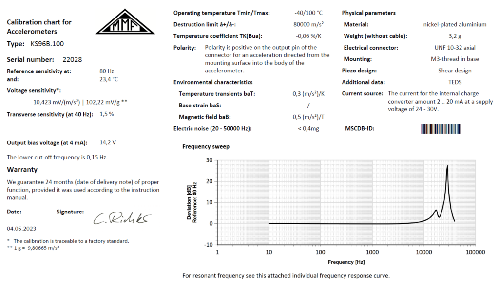
The following sections explain the parameters used in the individual calibration sheets.
Sensitivity
A piezoelectric accelerometer with charge output can be regarded as either a charge source or a voltage source with very high impedance. Consequently, charge sensitivity or voltage sensitivity are used to describe the relationship between acceleration and output. In the individual characteristics sheet Metra states the charge sensitivity at 80 Hz and room temperature in picocoulombs per g or m/s² (1 g = 9.81 m/s²).
The sensitivity of accelerometers with IEPE output is stated as voltage sensitivity in millivolts per g or per m/s².
The total accuracy of this calibration is 1 %, valid under the following conditions: f = 80 Hz, T = 23 °C, a = 10 m/s², ICONST = 4 mA.
The stated accuracy should not be confused with the tolerance of nominal sensitivity which is specified for most accelerometers. The accelerometer model KS84.100, for instance, has ± 5 % sensitivity tolerance, referred to its nominal sensitivity of100 mV/g. Standard tolerance window for sensitivity, if not otherwisely stated, is ± 20 %. Hence the exact sensitivity of production accelerometers may vary from the nominal sensitivity within the specified tolerance.
Charge sensitivity decreases slightly with increasing frequency. It drops about 2 % per decade. For precise measurements at frequencies far from 80 Hz a recalibration in the required frequency range should be performed.
Before leaving the factory each accelerometer undergoes a thorough artificial aging process. Nevertheless, further natural aging cannot be avoided completely. Typical are 3 % sensitivity loss within the first 3 years. For a high degree of accuracy recalibration should be performed
Frequency Response
Measurement of frequency response requires mechanical excitation of the transducer. Acceleration is kept nearly constant over the frequency range by means of a feedback signal from a reference accelerometer and a control loop. Most accelerometers are supplied with an individual frequency response curve It shows the deviation of sensitivity in dB up to the resonance area. For example the upper 3 dB limit can be derived from this curve. It is usually at about 50 % of the resonance frequency. The 10 % limit can be found in the range of 1/3 the resonance frequency.
Metra performs frequency response measurements under optimum operating conditions with the best possible contact between accelerometer and vibration source practical In practice, mounting conditions will be less than ideal in many cases and often a lower resonance frequency will occur.
The lower frequency limit of IEPE accelerometers can be found in the linear frequency range given in the data sheet. It is stated for limits of 5 %, 10 % and 3 dB. For accelerometers with charge output we do not state a lower frequency limit since it is mainly determined by the external electronics.
The frequency response of IEPE transducers can be altered by long cables.
Transverse Sensitivity
A transducer will measure in its geometrical axis or in the marked direction(s). However, due to its design and material tolerances it also has a certain sensitivity in other directions. Transverse sensitivity is the ratio of the output caused by acceleration perpendicular to the main sensitivity axis divided by the basic sensitivity in the main direction. A figure-eight curve is obtained for transversal sensitivity
Its maximum deflection is the stated value. Transverse sensitivity is measured at f = 40 Hz. Typical are <5 % for shear accelerometers and <10 % for compression and bending types.
Maximum Acceleration
Usually the following limits are specified in the technical data:
- â+ maximum acceleration for positive output direction The test object moves towards the transducer.
- â- maximum acceleration for negative output direction The test object moves away from the transducer.
- âq maximum transverse acceleration
For charge output accelerometers these limits are determined solely by the construction. If one of these limits is exceeded accidentally, for example, by dropping the sensor on the ground, the sensor will usually still function. However, we recommend recalibrating the accelerometer after such incidents. Continuous vibration should not exceed 25 % of the stated limits to prevent wear. When highest accuracy is required, acceleration should not be higher than 10 % of the limits.
If the accelerometer is equipped with built-in IEPE electronics, the limits â+ and â- are usually determined by the output voltage span of the amplifier.
Linearity
The mechanical sensing elements of piezoelectric accelerometers have very low linearity errors. Within the stated measuring range the amplitude linearity error will usually be less than 1 %.
The situation is different for sensors with IEPE output. The sensor electronics will contribute additional errors, particularly at higher output voltages. Typically the linearity error will be less than 1 % at within 70 % of the maximum output voltage.
Operating temperature range
The upper temperature limit is determined by the Curie temperature of the transducer material, about 320°C for lead zirconate titanate ceramics. Above this temperature, the piezoelectric properties disappear. Since irreversible changes already occur below the Curie temperature, the upper temperature limit is defined by the fact that the sensitivity does not change by more than 3%. For bonded transducers and transducers with internal amplifier, the temperature limit is defined by the adhesives used an by the electronic components. Above 120 °C, only transducers with charge output, i.e. without integrated IEPE electronics, can be used due to the temperature sensitivity of electronic components. With a remote IEPE amplifier like the IEPE100 from Metra the sensor signal can be conditioned for transmission.
Temperature Coefficients
Apart from permanent changes, some characteristics vary over the operating temperature range. These influences can be calculated by means of temperature coefficients.
For charge transducers temperature coefficients are specified for charge sensitivity TK(Bqa) and inner capacitance TK(Ci). The temperature coefficient Bqa and Ci are valid with a 1.5 m cable having a capacitance of 150 pF.
For sensors with built-in IEPE electronics only the temperature coefficient of voltage sensitivity TK(Bua) is stated.
There is a simple way to reduce the temperature coefficient of charge mode accelerometers. Since the temperature coefficients of Bqa, Bua and Ci are different, the temperature behavior can be compensated by a capacitor. It is a serial capacitor for charge amplification or a parallel capacitor for high impedance voltage amplification. This capacitor is calculated to:

This can be a useful improvement in the case of fluctuating temperatures. It needs to be considered, that the total sensitivity will become lower after compensation.
Temperature Transients
In addition to the temperature characteristics mentioned above, accelerometers exhibit a slowly varying output when subjected to temperature transients. The cause is the so-called pyroelectric effect. This phenomenon is specified as temperature transient sensitivity baT.
The values for baT stated in the datasheets are calculated from the electric output after a sudden temperature change measured with a lower frequency limit of 1 Hz.
To avoid this problem, shear type accelerometers should be chosen for low frequency measurements. In practice, they are approximately 100 times less sensitive to temperature transients than compression sensors.
Temperature jumps manifest themselves as error especially in the frequency range below 10 Hz. This applies in particular to sensitive measurements with compression transducers. Transducers based on the bending principle lie between shear and compression transducers in terms of temperature transient sensitivity. An improvement can often be achieved by thermal insulation of the sensor with styrofoam or similar. These interferences can be eliminated also by the selection of the lower cut-off frequency at the measuring amplifier. If measurements below 10 Hz are to be carried out, the use of transducers based on the shear principle is generally recommended.
Base Strain
When an accelerometer is mounted on a structure which is subjected to strain variations, an unwanted output may occur. It results from strain transmitted into the piezoelectric material. This effect can be described as base strain sensitivity baS.
The stated values baS are determined by mounting the sensor on a bending beam oscillating at 8 or 15 Hz.
Base strain output usually occurs at frequencies below 500 Hz. Base strain interference is difficult to compensate because it manifests itself in a signal similar to the measured acceleration. Shear type accelerometers have extremely low base strain sensitivity and should be chosen for strain-critical applications.
Magnetic Fields
Alternating magnetic fields act by induction and magnetostriction in the sensing element. Both influences are combined in the magnetic field sensitivity baB.
The stated values of baB are measured at the magnetic flux density B = 0,01 T and a frequency of f = 50 Hz.
Generally, accelerometers with stainless steel cases provide better protection against magnetic fields than accelerometers with aluminum cases.
The magnetic field sensitivity of piezoelectric accelerometers is relatively low and can usually be neglected. Magnetic fields can interfere in the vicinity of electrical machines with f = 50 Hz and their multiples.
A prerequisite for low interference in the presence of electromagnetic fields is also good cable shielding. This is particularly important for sensors with charge output.
In this context, it is also important to avoid ground loops. For long measuring cables or multi-channel applications, insulated mounting of the transducer is recommended. Some transducers have cases isolated from signal ground. We also recommend to use isolating flanges which are offered as accessory part.
Sound Pressure
High sound pressure level may caus deformation of the transducer case, which acts into the sensing element. Acoustic sensitivity is stated as baP in some datasheets.
Sound pressure sensitivity baP is measured at an SPL of 134 dB. The values are related to a sound pressure of 1 kPa (154 dB), which is far above the pain threshold and practically only occurs with shock waves.
Acoustic noise only contributes measurement errors at very high sound levels. Acoustic noise sensitivity should not be confused with the sensor response to pressure induced motion of the structure on which it is mounted.
Noise and Resolution
A piezoelectric sensing element can be regarded as purely capacitive source. Therefore, the sensor itself is free of intrinsic noise. The only noise contribution is caused by the temperature motion of electrons in the built-in the electronic circuit. Consequently, a noise specification makes only sense for IEPE compatible sensors.
The intrinsic noise determines the resolution limit of the sensor. Signals below the noise level cannot be measured.
The signal-to-noise-ratio Sn is a measure of the error caused by noise. It is the logarithm of the ratio of the measured signal level (u) and the noise level (un):

The intrinsic noise of IEPE compatible accelerometers mainly depends on the frequency.
Below about 100 Hz it has the typical 1/f characteristics. Above 100 Hz the noise level is nearly independent of the frequency. The following illustration shows a typical noise spectrum of an IEPE compatible accelerometer:
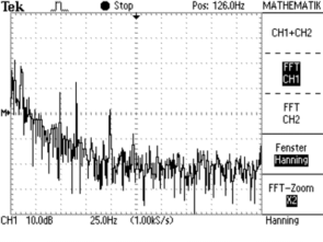
It is useful to state the noise of an accelerometer as equivalent acceleration level. For this purpose, the noise voltage (un) is divided by transducer sensitivity (Bua). The result is the equivalent noise acceleratio (an):

While un only depends on the electronic circuit which is similar for all sensor types, the sensitivity of the piezoelectric sensing element will directly influence the equivalent noise acceleration. It can be seen that a transducer equipped with a very sensitive piezo system will provide the highest resolution.
T enable an estimation of the resolution limit of the transducer, most datasheets specify the acceleration signal equivalent to noise an as an RMS value over the linear frequency range as well as noise densities for selected frequencies.
Example of a noise statement:
| Wide-band noise (RMS) | an wide band | < 14 µg (0,5 to 1000 Hz) |
| Noise density 0,1 Hz | an1 | 3 µg/sqrt(Hz) |
| Noise density 1 Hz | an2 | 1 µg/sqrt(Hz) |
| Noise density10 Hz | an3 | 0,3 µg/sqrt(Hz) |
| Noise density 100 Hz | an4 | 0,1 µg/sqrt(Hz) |
To find the equivalent noise acceleration in a frequency range of interest, select the noise density of the lowest frequency in the frequency range under consideration and multiply it by the square root of the difference between the upper and lower frequencies.
For the evaluation of the intrinsic noise of an entire measuring chain the noise of all components including signal conditioners and other instruments has to be considered.
Accelerometer and instruments need to be selected carefully in terms of noise when lowest vibrations are to be detected. Examples are building vibration monitoring and the operation of vibration-sensitive equipment (VC and Nano criteria).
Inner Capacitance
The inner capacitance Ci in the individual calibration sheet only for accelerometers with charge output. It can be relevant if the transducer is used with a high impedance voltage amplifier. The stated inner capacitance value includes the 1.5 m standard sensor cable. This cable capacitance is stated separately in the calibration sheet. Its value has to be deducted from the sensor capacitance to obtain the actual inner capacitance.
IP Rating
The IP ratings according to IEC 60529 characterize the suitability of a product for given environmental conditions. The first digit of the IP number means the shielding from the insertion of objects and dust. The second digit marks the protection against humidity.
| Number | First | Second |
| 0 | No protection against hand or body contact | No protection against humidity |
| 1 | Maximum object dimension which can be inserted is 50 mm | Equipment is protected against vertical drops fall |
| 2 | Maximum object dimension which can be inserted is 12 mm | Equipment is protected against drops falling with 15° slope regarding the vertical axis |
| 3 | Maximum object dimension which can be inserted is 2.5 mm | Equipment is protected against spraying water falling with 60° slope regarding the vertical axis |
| 4 | Maximum object dimension which can be inserted is 1 mm | Equipment is protected against splashing water coming from any direction |
| 5 | Inserted dust may not overlay equipment parts | Equipment is protected against water jetting (IP65) |
| 6 | Equipment is protected against powerful water jetting (IP66) | Equipment is protected against powerful water jets (IP66) |
| 7 | – | Equipment is protected against temporary immersion (IP67) |
| 8 | – | Equipment is protected against permanent immersion in given pressure (IP68) |
| 9k | – | Protection against water for high pressure and steam jet cleaning (IP69k) |

 Signal Conditioners
 Vibration Meters
 Vibration Calibrators
 Human Vibration
 Building Vibration
 PC Data Acquisition
 Cables and accessories