Theory and Standards
Would you like to familiarize yourself with the basic concepts of piezoelectric vibration measurement technology? By means of the provided information you will be able to select, mount and connect a vibration transducer. If you do not yet have any experience with piezoelectric vibration transducers, we recommend reading these pages in sequence as a learning course.
9. TEDS
Intelligent Accelerometers to IEEE 1451.4
Introduction
The standard IEEE 1451complies with the increasing importance of digital data acquisition systems IEEE 1451 mainly defines the protocol and network structure for sensors with fully digital output. Part IEEE 1451.4, however, deals with “Mixed Mode Sensors”, which have a conventional IEPE compatible output, but contain in addition a memory for an “Electronic Data Sheet”. This data storage is named “TEDS” (Transducer Electronic Data Sheet). The memory of 64 + 256 bits contains all important technical data which are of interest for the user. Due to the restrictions of memory size the data is packed in different coding formats.
The Transducer Electronic Data Sheet provides several advantages:
- When measuring at many measuring points it will make it easier to identify the different sensors as belonging to a particular input. The measuring system reads the calibration data automatically. Till now it was necessary to have a data base with the technical specification of the used transducers, like serial number, measured quantity, sensitivity etc. It is not necessary to mark and track the cable, which takes up a great deal of time.
- The measuring system reads the calibration data automatically. Before it was necessary to have a data base with the technical specification of the used transducers, like serial number, measured quantity, sensitivity etc.
- The sensor self-identification allows to change a transducer with a minimum of time and work (“Plug & Play”).
- Sensor datasheets often get lost. The TEDS sensor contains the essential technical data. Therefore, you are able to execute the measurement, even if the data sheet is just not at hand.
The standard IEEE 1451.4 is based on the IEPE standard. Therefore, TEDS transducers can be used like common IEPE transducers. The block diagram shows the principle of TEDS.
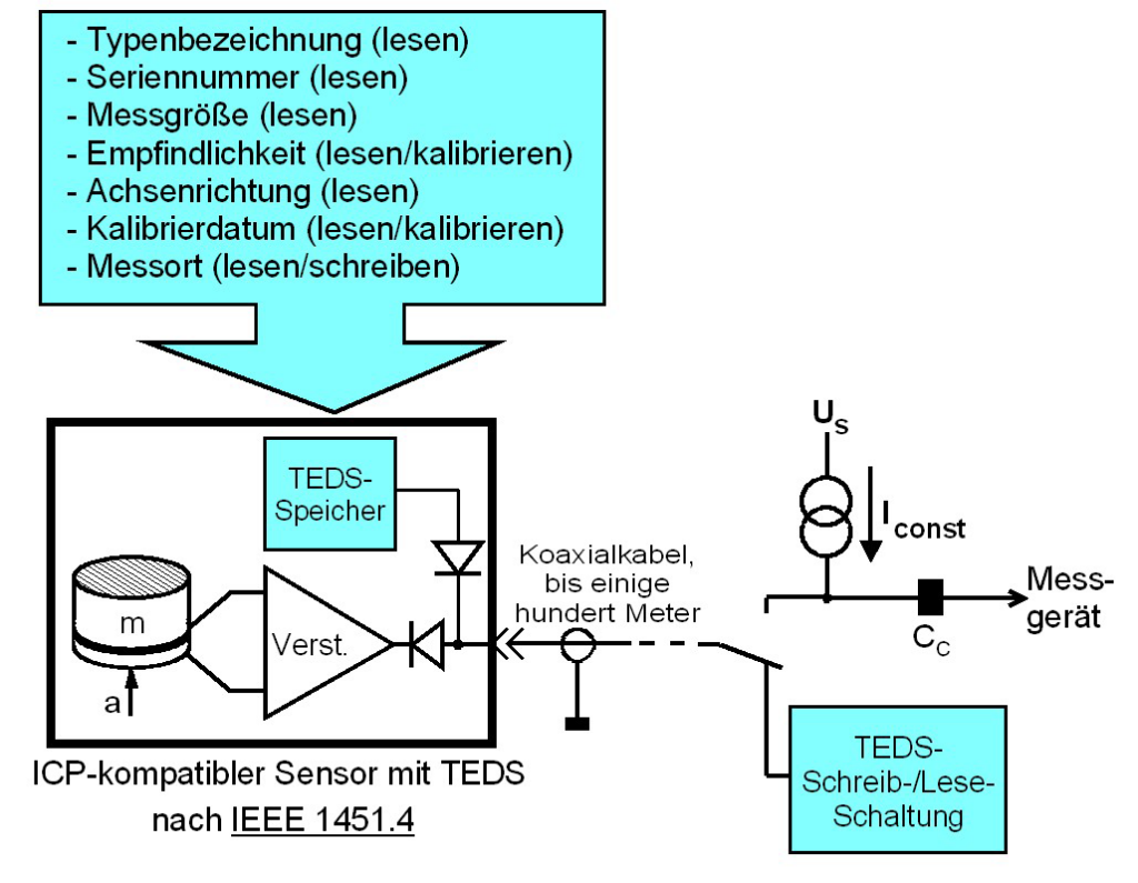
If a constant current source is applied, the sensor acts like a normal IEPE compatible sensor. Programming and reading the built-in non-volatile memory DS2430A or DS2431 is also done via the sensor cable. The communication uses Maxim’s 1-Wire® protocol. For data exchange TTL level with negative polarity is used. This makes it possible to separate analog and digital signals inside the sensor by two simple diodes.
Metra’s 8-channel IEPE signal conditioner M208A and the charge/IEPE amplifiers M72R1/M72S1 provide TEDS support with automatic transducer sensitivity normalization.
Sensor Data in TEDS Memory
Basic TEDS
A 64 bit portion of the memory is called application register. It includes the so-called Basic TEDS with general information to identify the sensor: Es enthält grundlegende Informationen zur Identifikation des Sensors:
- Model and version number: Metra stores in this location a coded model number. The actual model number, for example “KS78C100”, can be decoded by means of a *.xdl file to IEEE 1451.4 standard, the so-called “Manufacturer Model Enumeration File” which can be found in the download section of our web pages.
- Serial number: This is the actual serial number of the sensor which can be found on its case.
- Manufacturer code: A manufacturer-specific number assigned by IEEE. Metra’s manufacturer number is 61. A complete list of manufacturer codes can be found here: http://standards.ieee.org/develop/regauth/manid/public.html
Basic TEDS can exclusively be modified and stored by the manufacturer.
Template No. 25
Calibration data is stored in a 256 byte memory section. The arrangement of data is defined in TEDS templates. For accelerometers in most cases the standard template no. 25 will be applied. Some switch bits determine whether the memory includes a transfer function or not. It additionally includes typical data like resonance or lower frequency limit. In detail, template no. 25 includes the following data:
- Sensitivity in V/m/s²: Sensitivity value at reference conditions according to the supplied calibration chart
- Calibration frequency of sensitivity in Hz
- Lower frequency limit in Hz: Typical value according to sensor data sheet
- Measuring direction: Relevant for triaxial accelerometers (0 = X; 1 = Y; 2 = Z; 3 = no data)
- Sensor weight in grams
- Polarity of output signal for positive acceleration: 0 = positive, 1 = negative
- Low pass frequency in Hz (if the sensor includes a low pass filter)
- Resonance frequency in Hz: Typical value according to sensor data sheet
- Amplitude slope in percent per decade
- Temperature coefficient in percent per Kelvin: Typical value according to sensor data sheet
- Calibration date (DD.MM.YY)
- Initials of calibrating person (3 capital letters)
- Calibration interval in days: Recommended time until next calibration
Unless otherwise requested by the customer, Metra uses the version without transfer function.
This data can be modified by the calibration lab of the manufacturer or later by other calibration labs.
In addition, TEDS memory provides some bytes for application specific data which may be entered by the user:
- Measurement point ID (1 to 2046)
- User text: 13 characters
Notice: In our Download section we offer a TEDS editor which can be used to read or modify the data stored in TEDS transducers.
Detailed description of Metra’s TEDS data: PDF

 Signal Conditioners
 Vibration Meters
 Vibration Calibrators
 Human Vibration
 Building Vibration
 PC Data Acquisition
 Cables and accessories